


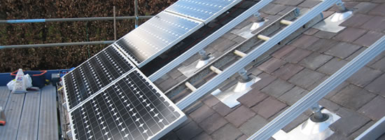
1.665Kwp Phonosolar Array using fronius IG15 Inverter, Abersoch, North Wales
GENERAL AND AC SIDE EARTHING
Background and main applicable UK standards
The earthing of an electrical system is one of the key safety elements for both system design and operation. The main process of earthing is to connect all parts which can become electrically charged to the general mass of earth. This provides a suitable path for fault current, and ensures that the voltage rise of the connected parts remains as close to earth potential as possible.
Within the UK, the earthing of an electricity supply system is governed by the following main legislation and regulations:
• The Electricity supply regulations [1]
• The Electricity at Work regulations 1989 [2]
• BS7430 – Code of practice for earthing [3]
• IEE Wiring regulations – 16th Edition – BS7671 [4
Contradictory Earthing Requirements
It is important to understand that the optimum earthing strategy for any system is often a compromise between that which can be achieved, and that which has to be. This problem is significantly exacerbated since earthing systems are called upon to provide different protective roles. Typically, these roles are:
• Connection of all associated metalwork to ensure that all potentials are equal
• Connection of neutral conductor to ensure a known voltage reference
• Connection of all equipment to ensure correct protection co-ordination
• Bonding of external exposed metalwork to ensure minimal touch potential hazard
These few examples all utilise a connection with earth, but for many different reasons. One of the safest philosophies, to ensure that no dangerous potential can be touched from associated and exposed metalwork, is to connect all metal parts together. From a protection perspective this is not an ideal solution, as the presence of multiple earth paths makes protection, co-ordination and discrimination difficult due to the large number of current loops. Also, fault current may be present in conductors and materials that are not designed to carry the size of fault current expected, and so such an earthing philosophy can be considered a considerable fire hazard.
The best earthing strategy therefore for one arrangement may not necessarily be the best for another, and so a trade off has to met which is both safe, and meets the necessary requirements.
For PV installations there are various factors which have to be taken into consideration for the earthing arrangement. The main objective however remains the same, in that the installation must be electrically safe under normal and possible fault conditions.
Class II Equipment
Today, some PV inverters and arrays are built to Class II electrical equipment
specifications. BS7671 state that these appliances must have reinforced or double
insulation, in addition to the standard insulation.
For most inverters, this extra level of isolation comes in the form of “Electrical
Separation” between the AC and DC side of the inverter. This separation is achieved with the use of an isolation transformer (conforming with BS3535-2), in principle a similar approach taken to domestic shaver supplies in bathrooms. This is sometimes referred to as “Galvanic Separation” .
This isolation from earth will prevent electric shock due by providing no return path for any fault current to flow, and hence complete a fault current circuit. This approach does assume however that the contribution from stray earth leakage resistance’s and coupling capacitance’s from imperfect insulation is zero or negligible. These factors must therefore not be overlooked when installing any system, with an objective to minimise any stray coupling impedances and capacitances. BS7671 does reference that ‘Earth Free’ bonding is often allowed, but only in specific areas. This arrangement requires that all exposed metal parts are connected together, but NOT to earth. This type of arrangement is often referred to as a ‘Faraday Cage’.
Extreme care however must however be taken in these situations, since any earthed equipment must not be brought into the earth free zone, or be capable of being touched from within the zone. A notice is therefore required to be installed, to warn that any bonding conductors within a certain location must not be brought into the area, or bonded to.
The use of Class II equipment and inverters is not yet common place, and so both Class I and Class II systems should be considered when designing the earthing of a PV system. It is recommended that Class II equipment and cabling be used wherever possible. Where the inverter is Class I, then the outer metallic casing should be bonded to the consumers earthing terminal. Where the Inverter is Class II, then there is no need to bond the outer inverter casing.
Earthing conductors
Regulation 7 in the electricity supply regulations state that the following be used to ensure the minimum bonding conductor cross sectional area.
Table 2
Column 1 |
Column 2 |
Copper equivalent CSA of supply neutral |
Minimum copper equivalent CSA of |
35 sq mm or less |
10 sq mm |
> 35 sq mm but not more than 50 sq mm |
16 sq mm |
> 50 sq mm but not more than 95 sq mm |
25 sq mm |
> 95 sq mm but not more than 150 sq mm |
35 sq mm |
> 150 sq mm |
50 sq mm |
These requirements also agree with those given in the IEE Wiring regulations and are also valid for PME installations. It is also specified within the IEE Wiring regulations that any protective bonding conductor must have protective Green and Yellow insulation.
The protective conductor size can however be calculated more accurately. The main factor which influences the size is the fault current, which is governed by the supply voltage and the earth loop impedance. In may cases, calculation will often show that a smaller size to that recommended is perfectly adequate.